This very detailed Tutorial is intended to expose the SigScribe4 user to most aspects of designing a MODRATEC interlocked Lever Frame. It is a stand-alone unit and does not assume that the reader has previously completed the Simple Tutorial.
![]() ®
®
|
This very detailed Tutorial is intended to expose the SigScribe4 user to most aspects of designing a MODRATEC interlocked Lever Frame. It is a stand-alone unit and does not assume that the reader has previously completed the Simple Tutorial. |
|
SigScribe4 - Documentation - Advanced Tutorial
Using SigScribe4 - Advanced TutorialThis Tutorial is designed to stand alone. It does not assume that you have already completed the Simple Tutorial. Consequently, there is some degree of overlap between the two.
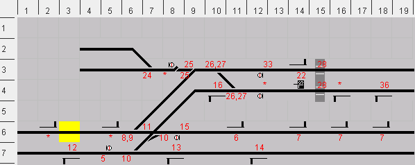
Working through the following tutorial should give you a good working knowledge of how to apply SigScribe4 to your personal requirements. Most features of SigScribe4 are demonstrated. Arrange your windows so that you can easily read this document while working on SigScribe4. You may find it helpful to open the Symbols Panel. Click here to open it now. Starting SigScribe4 The main window for SigScribe4 should now be visible. It will be annoyingly showing 18 tiles x 6 tiles. The remaining tiles can be seen by using the horizontal and vertical scroll bars, but to make life easier, let's resize the window. This can be done by moving the mouse pointer close to an edge or corner where it will change to the resizing arrows. Drag to the desired size while holding the left mouse button down. The scroll bars on the Signal Diagram panel will disappear when all tiles are visible. Mac users: Drag the grow box at the bottom right corner. Note that when SigScribe4 is resized the detail window always remains the same size, the Lever Frame will change in width but not height, and the Signal Diagram will fill all remaining space. On the title bar at the top of the SigScribe4 window you will note the title of the programme together with the name of the file holding the current data. It's called "unsaved.ss4". All SigScribe4 data files in which you will store your designs have the suffix ".ss4". The current file is called "unsaved" because the current data (not that there is any yet) has not been saved. Let's create a file to hold this tutorial design. Move the mouse pointer to the menu bar - the one just below the title bar (Mac users: top of screen) - to the word "File". If you click on the word a menu will open. You can also open any of these menus without the mouse by holding down the "alt" key while also pressing the key for the underlined letter, in this case "F" (doesn't apply to Mac.). Having opened the menu, you can use the mouse to move to the "Save" item. Notice that the 'S' is underlined. Once the menu is open, you need only type the letter 'S' to select 'Save' (doesn't apply to Mac.). Also, there is a note to the side indicating "Ctrl-S" (Mac - "apple-S"). This is a shortcut to that menu item that can be used anytime without even opening the menu. Simply holding down the "Control" (Ctrl) key while you press the "S" key is enough to save a design. Since you have your mouse pointer poised over the Save item on the menu, click it, and a dialog box will appear. The "Save" dialog box, by default, will save files in a sub-directory called "Signal Diagrams". It also gives you the opportunity to create a new directory (folder) if you wish. Enter a name for the file you are about to create, and then click the "Save" button. You will notice that the new file name is now written in the title bar. As you work through the tutorial, get into the habit of pressing ctrl+S (apple+S) occasionally to save your work. Just a further comment about saving files. Once a file exists for the current design, "Save" will not trigger the dialog box. However if you use "Save as..." (ctrl+shift+S) (apple+shift+S) then the dialog will appear so that you can specify a new name. Now we're ready to draw a Signal Diagram. Design Step 1 - Draw the Signal DiagramThis is what the Signal Diagram for this tutorial should ultimately look like: We'll start with some straight horizontal lines to represent the main running lines. You do this by mouse using alt+left+drag. Move the multi-colour marker to tile [4, 3], that is column 4, row 3. Now hold down the "alt" key on the keyboard, press the left mouse button, and drag the mouse to the right until all of the tiles in row 3 from column 4 to column 19 are marked. Release the mouse button and "alt" key and a track will appear in the tiles that were marked. Notice that it doesn't matter if you drift vertically off the line you are drawing - only the horizontal movement is sensed. Hint: A handy way to draw a single tile of horizontal track is to use alt+click+drag with a vertical movement of the mouse. If you need to delete a tile, point to it with the marker then click the right mouse button. This will trigger a popup menu which includes the option to delete a tile. Draw further horizontal lines as follows.
Now we'll add some bends. Go to tile 6, 2. Hold down the shift key on the keyboard. This will prevent the marker from moving with the mouse pointer. It also allows us to mark the entry / exit directions for the track formation we want at this tile. Still holding down the shift key, point to the green square on the left of the tile marker (direction west) and click the left mouse button. That square will change to blue. Now do the same with the bottom right yellow square (direction south-east). And finally click on the magenta centre square. If you did not release the shift key throughout this procedure, a piece of bent track should have appeared joined to the horizontal track at [5, 2]. In a similar way, place a bend at [9, 4] running from south-west to east. A set of points is next - at tile [7, 3]. It doesn't matter that there is already a piece of track at this tile - it will simply be overwritten. Again, use the multi-coloured marker and specify three directions - north-west, west and east. Place additional points as follows:
At [7, 6] place a diamond crossing with single slip. You need to specify four directions for this, W, SW, E, NE. Do this to create the diamond crossing. To understand the next step, look at the Symbol Table for 'Bridges, Crossings'. You will notice that beginning with the "seed" that we've just created, the diamond crossing, we can convert it to any of the other formations shown by pressing "H" and / or "V" on the keyboard. To convert to the required single slip, place the multi-coloured marker on the tile and simply press "V" twice. (If nothing is happening, it is probably because you need to return focus to the SigScribe4 window. This can be done by clicking the mouse button anywhere within the SigScribe4 window.) Follow a similar process to place at [8, 3] a set of catch points with ground signal. Refer to the Symbol Table for 'Signals, etc...' to see how to convert a piece of horizontal plain track into the other elements shown. We need to press "H" three times and "V" once. Now place level crossings at [15, 3] and [15, 4]. Complete the track layout by placing diagonal tracks at [8, 4], [7, 5] and [8, 5]. Add signals to horizontal plain track. Refer to the Symbol Table 'Signals, etc...'. Place a post mounted signal at [2, 6]. Make sure that it is facing the correct way for left hand running. (You pressed "V" twice, didn't you?) Add further post signals facing the correct way at [3, 7], [5, 6], [8, 7], [10, 4], [11, 6], [12, 7], [14, 3], [14, 6], [16, 4], [16, 6], [18, 4] and [18, 6]. Add a ground signal facing the correct way at [12, 4]. Add ground signals facing the wrong way at [5, 7], [8, 6] and [12, 3]. Design Step 2 - Check the "normal" setting for all points.The diagram we've drawn represents a double track junction with a trailing lead from the secondary line to sidings. A facing crossover on the secondary line allows direct access to the sidings. The single slip at the junction forms half of a trailing crossover in the primary line. The setting of points on the Signal Diagram at this stage of design must correspond to the operating lever being in the "normal" position, that is away from the operator. Normal setting for points should be the main or more important track. Two sets of points need to be modified. Firstly, the trailing points for the sidings [9, 3]. It is envisaged that these points would be operated from the same lever as the adjacent catch points. So we need to change the state of the trailing points. Refer to the Symbol Table 'Simple Turnouts'. You will notice that the normal state of these points can be altered by an "H" keystroke. Make the necessary adjustment to your design. Next, consider the single slip. It combines a diamond crossing with two sets of points. The points to the right of the diamond are correctly set to the main line, but the points to the left of the diamond should be normal for the secondary main line. Referring to the 'Bridges, Crossings' Table you will see that pressing "H" twice brings about the desired change. Make this adjustment to your diagram. Design Step 3 - Ensure that all anticipated train movements are correctly signalled.There is one intended movement on this layout which is not
correctly signalled. It is anticipated that a train in the sidings could push
out onto the secondary line, across the facing crossover from where it could
proceed forward towards the junction. The error is that there is nothing to
limit how far the train is permitted to travel in the wrong direction towards
the level crossing. A shunt limit marker At [14, 4] place a shunt limit indicator facing the wrong direction. Design Step 4 - Specify the detail for all signals.Move the marker to tile [2, 6]. This is the location of distant signals. Details are specified in the detail window at the bottom right of the screen. To open it you can either double left click with the mouse pointing at the required tile, or right click on the tile for the popup menu from which you can select "Detail View". The detail view has a 4 x 4 grid in which signal arms for semaphores or colour light signal heads can be placed. The process is similar to that used above for creating track elements from "seeds". In this case, the only seed is an empty tile. The current tile is indicated by a grey rectangle. Refer to the Symbol Table 'Post-mounted Signals'. We will use semaphore distant signal arms (yellow & black), so we need to press "H" twice. We need to indicate two arms corresponding to each of the routes available at the junction. In one sense it doesn't matter where we place the arms, as long as there are two. But life will be much less confusing if they are placed as logically as possible. In the real world, the arm to the right would correspond to the primary (straight ahead) route and the left to the secondary (diverging) route. The relative importance of each route would also be conveyed by the left arm being mounted lower than the right. In our case, place one distant arm in the first column and second row, and the other at the top row of the second column. Now move to tile [5, 6] on the Signal Diagram and open the detail view for that signal. We need to place three arms. At the top of the second column place a standard stop arm (the larger red and white arm, which from now on I will call a "home" arm for simplicity). This arm mirrors the similarly placed distant arm at the previous location and is used to show clear for the straight ahead route. Next place a home arm in the second row of the first column, again mirroring the previous location. Then place below the second home arm, a distant arm. This is used to give advance warning of the state of the home signal before the level crossing. (We are imagining that in the real world this layout is under the control of two signal boxes - one in the vicinity of the level crossing and the other near the junction. Again in the real world, the distant signal at [5, 6] would be controlled from the level crossing box and slotted with the home signal above it controlled from the junction box.) Specify arms for further post signals as follows:
Specify ground signals in a similar fashion. Refer to the Symbol Table 'Ground Signals'.
Design Step 5 - Specify facing point locks.For this tutorial, we will specify independent facing point locks (FPLs) at the junction points [6, 6] and the facing crossover [10, 3] and [11, 4]. We will also specify combined locks for the points at [8, 3] and [9, 3]. Move the marker to [6, 6] and right click for the popup menu. You'll find the option "Toggle FPL". Click it and the FPL for these points is now active as indicated by the 0,0 lever designation. Activate the FPLs at [10, 3] and [11, 4] in a similar way. We don't activate the FPLs at [8, 3] or [9, 3] since they are imagined to work from the same lever as the points. All we do is use a different coloured lever. Move the marker to [7, 6], the single slip. We are not specifying FPLs here but its worth seeing how to. Select "Toggle FPL" from the popup menu and a detail view will open where individual FPLs can be activated by a simple mouse click. Close the detail window by left clicking anywhere on the Signal Diagram The Signal Diagram is now complete. Design Step 6 - Design the Lever Frame.Firstly count how many levers you will need. You need one per signal arm (or group), one per level crossing, one per set of points or crossover, and one per FPL (or group of FPLs). For this tutorial there are 22 signal arms, 1 signal group, 6 sets of points, 1 (double track) level crossing, 1 FPL and 1 FPL group, a total of 32 levers. SigScribe4 always starts with six levers in the Frame. To get the 32 we require, go to the panels menu and select Edit Lever Frame. A dialog box will appear allowing you to select the number of levers required. Click on the selection box to see the options. We need 32, so select 36. You should now have 36 levers although you might be seeing only 15. The scroll bar below the Lever Frame allows you to see the hidden ones. SigScribe4 always allocates levers in multiples of six for compatibility with the MODRATEC Lever Frame. The spare levers are not a big issue. Most Lever Frames in the real world have spares either allowing for future expansion or as the result of layout simplification. And it's always handy to have a lever or two that the very young enthusiast can be permitted to operate indiscriminately! The technique for changing the colours of levers is similar to selecting signal arms. The "seed" is the white (spare) lever. Refer to the Symbol Table 'Levers' to see how to make the transformations. A grey rectangle shows the current lever. Point to lever 1. We want it to be yellow so press "H" three times. Change the colours of the rest of the levers as follows:
Design Step 7 - Connect the levers.To connect levers to track elements, both the Signal Diagram and Lever Frame must be protected. Do this now from the window menu. You will notice that the background of each changes to grey. Point to lever 1. A yellow rectangle indicates the current lever. Right click for the popup menu and select "Connect". A red rectangle indicates that the current lever is ready to be connected. Note also the cancel bar at the bottom of screen. Move to the Signal Diagram and point to the signal at [2, 6] and right click for the popup menu. Select either "Connect (left)" or "Connect (right)". The signal detail window will open. Move to the detail window and point to the lower left arm. Right click for the popup menu and select "Connect". The "1" below the arm indicates that it is connected to lever 1. The number below the levers indicates the number of devices connected to that lever. That completes connections to lever 1, so click the cancel bar. Next select lever 6 for connection. This will be connected to the signal at [11, 6]. This time, when you select either of the "Connect" options from the popup menu, the connection will be completed without using the detail window. This is because there is only one arm to be chosen. Click the cancel bar to enable further connections. Select lever 8 for connection, then move to the points at [6, 6]. Because there can be only one points lever connection to this element, you can connect with either "Connect" option. Cancel when complete. Select lever 10. This will operate the crossover at [6, 7] and [7, 6]. You need to connect it to each location, but be careful at [7, 6] to choose the "Connect (right)" option in order to connect to the points to the right hand side of the tile. Just for fun, try operating the levers that have been connected to check that the corresponding devices operate as expected. You can either point to a lever and shift+left+click it, or right click for the popup menu and select "Change". You should notice that only half of crossover 10 works until the left side of the slip is connected. Complete the connections as follows:
Puzzle: In the true spirit of a tutorial, here's a puzzle for you. With all other levers normal, pull lever 20 or lever 21 and see what happens. Can you guess why that happens, and why it won't be a problem in our completed design? Design Step 8 - Define routes.Routes are the sections of track which a train is authorised to occupy by a clear signal indication. Routes can contain sub-routes. Sub-routes are also routes in their own right. Specifically for our purposes, subsidiary signal routes can be sub-routes of standard stop signals and standard stop signal routes can be sub-routes of distant signals. Because of these sub-route considerations it is sensible to define subsidiary (shunt) signal routes first, then standard stop (home) signal routes, and finally distant signal routes. Shunt signal routes extend to the next facing shunt or home signal or "Shunt Limit" notice. Home signal routes extend to the next facing home signal or the next distant signal. Distant signal routes extend past the next facing distant signal to the first facing home signal. Activate the popup menu for lever 5 and select "Define Route". After a short time the current route is indicated on the Signal Diagram. As it stands, it's obviously the wrong route since it authorises a train to proceed freely in the wrong direction on a main running line! The intended route for signal 5 is via the crossover and up to signal 6, the stop signal at [11, 6]. Reverse the crossover points (10) and see what happens. Another wrong route. Now change points 11. The route is now correctly defined, but a degree of protection can be added. Consider what might happen if a train were approaching the junction from the left and overran the junction signals. It would collide with a train obeying signal 5! That possibility can be eliminated by setting points 8 at reverse in order to divert a runaway. To add this protection (some railways would do this and others would not), while in the route definition mode for lever 5, pull lever 8 and then activate the popup menu for lever 8 and select "Include Points". Since there is a facing point lock for points 8, pull lever 9 to include this in the route definition. (Not all route definitions are this complicated!) Route definition for lever 5 in now complete so click the cancel bar. There is an alternative method to add such diversionary (or flank) protection - interlocking points. We could make it a "rule" that points 10 can be reversed only if points 8 are reversed and locked. Let's include this points interlocking in our design. Activate the popup menu for lever 10 and select "Interlock Points". Now reverse lever 8 and then activate its popup menu and select Include Points. Finally activate the popup menu for lever 9 and select "Include FPL". Click the cancel bar. Now that the diversionary protection has been implemented by interlocking the points we can simplify our route definition for signal 5. Popup the menu for lever 5 and select "Clear Route". Now pop it up again and select define route, reverse levers 10 and 11, and the definition is complete. Another situation where points interlocking is useful is illustrated by points 10 and 11. There is no purpose in reversing points 11 unless points 10 are also reversed. From the popup menu for lever 11 select "Interlock Points", then reverse lever 10, activate its popup menu and select "Include Points". We'll now move to lever 32, another shunt signal. Open the detail window for this signal by double clicking [12, 4] on the Signal Diagram. You will see that signal 32 in one of a pair of discs. Being the lower of the pair, it applies to a route to the right. It is to permit access to the sidings. Activate the "Define Route" mode for lever 32. Set the route to the sidings by reversing crossover 26 and points 25. You'll see that the route currently exists no further than the start of the crossover. These points have facing point locks, so the route is not valid until these are locked (lever 27). At present the route includes points 24 at normal. We may wish the signal to give clearance to enter either siding. We could provide a third disc to allow a separate route for each siding, or we could leave points 24 out of the interlocking (free), or we could lock points 24 for both possibilities. We'll do the last. From the popup menu for lever 24 select "Both N & R". (Be very cautious about using this method in your own designs!) Click the cancel bar, and now define the route for lever 31. It authorises movement up to signal 16. Don't forget the FPL! In order to demonstrate the use of "free" points, define the route for signal 33 for movement into the sidings. DO NOT include lever 27 since this movement is not a facing movement for points 26. From the popup menu for 24, select "Free". Open the detail window for [8, 3]. Define the route for the upper disc for movement up to signal 22. For the lower disc, the route is via the facing crossover and up to the shunt limit indicator. Open the detail window for [16, 4]. Define the route for the shunt signal for movement up to the signals at [12, 4]. Define the route for the final shunt signal (15) for movement via the trailing crossover up to signal 12. Move to lever 35 controlling a home signal at [16, 4]. This will illustrate the process of including a sub-route. The route will extend to signal 16. When you activate the define route mode, you will notice that the route stops at the ground signals at [12, 4]. The appropriate shunt signal route needs to be included. If necessary open the detail window for [12, 4] to remind yourself of which shunt disc controls the route to signal 16. You're right! It's number 31. From the popup menu for lever 31, select "Include Sub". Complete the route definitions for the home signals as follows:
And now, the distant signals:
It only remains to define the route for the intermediate block signals 7 as "off diagram". Congratulations! All routes are now defined. Design Step 9 - Test Interlocking.From the interlocking menu select "Set Interlocking". Provided that you have not inadvertently defined any impossibilities in your design, after a few seconds of calculating, the interlocking will be implemented and simulated on the Lever Frame. Below the levers the indicators L or F mean that the corresponding lever is locked or free. For affordable and effective Web Hosting, MODRATEC uses and recommends Hosting Bay |
|
© 2004-2006 MODRATEC, Australia. All rights reserved.
 .. The "Open SigScribe4" dialog box asks you to enter
the size you need for your Signal Diagram, that is, the area in which you will
draw the track layout and signalling features. It refers to the number of columns wide and rows high. It will always present suggested figures of 30 and
15. You can accept these numbers or replace them with your own. For
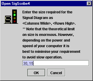
this tutorial we will use 19 columns and 7 rows. Type over the existing numbers with the new ones. Type 19, 7. (Hint: The two numbers can be separated by any string of "non-numerals".) When complete, click "OK" to continue, or alternatively, just hit the 'Enter' key. Clicking "Cancel" or the quit button at the top of the dialog box will abort the session.
.. The "Open SigScribe4" dialog box asks you to enter
the size you need for your Signal Diagram, that is, the area in which you will
draw the track layout and signalling features. It refers to the number of columns wide and rows high. It will always present suggested figures of 30 and
15. You can accept these numbers or replace them with your own. For
this tutorial we will use 19 columns and 7 rows. Type over the existing numbers with the new ones. Type 19, 7. (Hint: The two numbers can be separated by any string of "non-numerals".) When complete, click "OK" to continue, or alternatively, just hit the 'Enter' key. Clicking "Cancel" or the quit button at the top of the dialog box will abort the session.